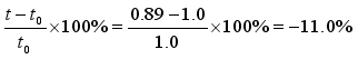
The end surfaces of large storage tanks used in various industries are often composed of thin-walled metallic spherical cap structures. The ability to process these components at a low cost and with high manufacturing precision is an important research challenge. In this study, a new integrated free-bulge forming method is proposed to fabricate thin-walled metallic spherical cap structures. This method involves fixing the perimeter of a circular forming sheet, applying internal water pressure, and uniformly bulging the central portion of the sheet to achieve a spherical cap structure. To analyze the forming performance of the proposed method, formulas for calculating the plastic strain and average thickness during the process of forming the spherical cap from the circular sheet are derived, enabling a clear understanding of the workable range of the free-bulge forming method. Additionally, by deriving a prediction formula for the internal water pressure required for the free-bulge of the spherical cap structure, the key process design factors are identified. For verification, a free-bulge forming device is developed, and thin-walled metallic spherical cap structures are processed. The results confirm that the spherical cap shape is sufficiently precise and can be stably produced using the free-bulge forming method. Furthermore, a specialized device for measuring the shape accuracy of the spherical cap formed using the proposed free-bulge method is developed, and the surface shape of the spherical cap structure is measured. The results show that the formed spherical cap shape has a maximum deviation of 2.3% from the theoretical shape, demonstrating adequate precision for practical applications. To further verify the processing performance of the free-bulge forming method, the thickness distribution of the processed thin-walled metallic spherical cap is measured along its diameter. The results show that, compared to the original thickness of 1.0 mm, the minimum thickness of 0.858 mm occurs at the center of the spherical cap, representing a thickness reduction rate of -13.2%. It is confirmed that the free-bulge method can be stably applied to typical thin-walled press materials.
| Published in | International Journal of Mechanical Engineering and Applications (Volume 13, Issue 3) |
| DOI | 10.11648/j.ijmea.20251303.11 |
| Page(s) | 86-97 |
| Creative Commons |
This is an Open Access article, distributed under the terms of the Creative Commons Attribution 4.0 International License (http://creativecommons.org/licenses/by/4.0/), which permits unrestricted use, distribution and reproduction in any medium or format, provided the original work is properly cited. |
| Copyright |
Copyright © The Author(s), 2025. Published by Science Publishing Group |
Spherical Cap Structure, Free-bulge Forming Method, Storage Tank, Spherical Shell, Metal Forming Sheet, Plastic Formability
 (1)
(1)  (2)
(2)  (3)
(3)  (4)
(4)  (5)
(5)  (6)
(6)  (7)
(7)  (8)
(8)  (9)
(9)  (10)
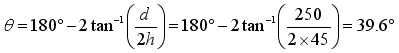
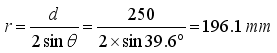
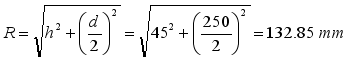
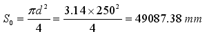
(10)  of the material. The internal hydraulic pressure at this point can be calculated as follows:
 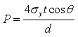 (11)
(11)  (12)
(12)  (13)
(13)  (14)
(14) FEM | Finite Element Method |
SPCC | Steel Plate Cold Commercial |
| [1] | Stoicescu, A. A., Ripeanu, R. G., Tanase, M., & Toader, L. (2025) Current Methods and Technologies for Storage Tank Condition Assessment: A Comprehensive Review. Materials, 18(1074). |
| [2] | Cirimello, P. G., Otegui, J. L., Ramajo, D., & Carfi, G., (2019). A major leak in a crude oil tank: Predictable and unexpected root causes. Engineering Failure Analysis, 100, 456-469. |
| [3] | Bagarello, S., Campagna, D., & Benedetti, I., (2024). A survey on hydrogen tanks for sustainable aviation. Green Energy and Intelligent Transportation, 100224. |
| [4] | Milovanovic, A., & Sedmak, A., (2018). Integrity assessment of ammonia spherical storage tank. Procedia Structural Integrity, 13, 994-999. |
| [5] | Lee, H. S., Yoon, J. H., Park, J. S., & Yi, Y. M., (2005). A study on failure characteristic of spherical pressure vessel. Journal of Materials Processing Technology 164, 882-888. |
| [6] | Malfroy, J., Steelant, J., & Vandepitte, D., (2025). A Design Guide to Tapered Conformable Pressure Tanks for Liquid Hydrogen Storage. Aerospace, 12(190). |
| [7] | Chatterji, S., Butenweg, C., & Klinkel, S., (2025). Unified force-based design approach for the seismic analysis and design of liquid storage tanks. Bulletin of Earthquake Engineering, 2025. |
| [8] | Drawer, C., Baetcke, L., Lange, J., Shang, Y., & Kaltschmitt, M., (2025). Novel concepts for metal hydride storage tanks - Numerical modeling, simulation and evaluation. Energy Conversion and Management, 327(119572). |
| [9] | Arabzadeh, V., Niaki, S. T. A., & Arabzadeh, V., (2018). Construction cost estimation of spherical storage tanks: artificial neural networks and hybrid regression - GA algorithms. Journal of Industrial Engineering International, 14, 747-756. |
| [10] | Oyelami, A. T., & Olusunle, S. O. O., (2019). Spherical Storage Tank Development Through Mathematical Modeling of Constituent Sections. Mathematical Modelling of Engineering Problems, 6(3), 467-473. |
| [11] | Chen, B, Huang, J. X., & Shen, Y, (2015). The Economic Design and Analysis for Mixed Model Spherical Tank Shell Angle Partition. Procedia Engineering, 130, 41-47. |
| [12] | Demir, K, U, Gokdag, I., Dagkolu, A., & Sahin, M, (2023). Shape and Size Optimization of an Aerospace Propellant Tank. 12th ANKARA International Aerospace Conference 13-15 Sep. 2023 Ankara TURKIYE, AIAC-2023-046. |
| [13] | Yu, Y., Xie, F., Zhu, M., Shuai Yu, S., & Li, Y., (2023). Design and Optimization of the Insulation Performance of a 4000 m3 Liquid Hydrogen Spherical Tank. Processes, 11(1778). |
| [14] | Ibrahim, A., Ryu, Y., & Saidpour, M., (2015). Stress Analysis of Thin-Walled Pressure Vessels. Modern Mechanical Engineering, 5, 1-9. |
| [15] | Adeyefa, O., & Oluwole, O., (2011). Finite Element Analysis of Von-Mises Stress Distribution in a Spherical Shell of Liquified Natural Gas (LNG) Pressure Vessels. Engineering, 3, 1012-1017. |
| [16] | Adibi-Asl, R., & Livieri, P., (2007). Analytical Approach in Autofrettaged Spherical Pressure Vessels Considering the Bauschinger Effect. Journal of Pressure Vessel Technology, 129, 411-419. |
| [17] | Luo, Y., Wang, Z., Wang, Q., Mao, H., Hong, Q., & Li, L., (2023). Improvement in Connecting the Structure of Spherical Crown Middle Head. Journal of Physics: Conference Series, 2450(012029). |
| [18] | Doan, M. L., Nguyen, V. T., & Tran, C. T., (2021). An analysis of In-Vessel Melt Retention strategy for VVER-1000 considering the effect of torospherical lower head vessel. Nuclear Engineering and Design, 371(110972). |
| [19] | Salman, M. A., Ismail, M. R., & Kahtan, Y. Y., (2018). Effect of Head Types on the Free Vibration and Fatigue for Horizontal LPG Pressure Vessels. Al-Nahrain Journal for Engineering Sciences, 21(04), 494-500. |
| [20] | Emegbetere, E., ThankGod, B., Oreko, B. U., Akene, A., Oghenekowho, P. A., Edward, B. A., (2021). Design and Analysis of a Butt Welded Pressure Vessel Reactor. Journal of Energy Technology and Environment, 3(2), 71-77. |
| [21] | Dandekar, A., Gordon, A., & Kulkarni, M., (2023). Numerical Analysis of Permanent Deformation in Pressure Vessels DUE to Weld Overlay. Proceedings of the ASME 2023 Pressure Vessels & Piping Conference (PVP2023), July 16-21, 2023, Atlanta, Georgia, USA. |
| [22] | Liu, C., & Bhole, S. D., (2002). Fracture behavior in a pressure vessel steel weld. Materials and Design, 23, 371-376. |
| [23] | Vukojevic, N., Sabanovic, K., Barlov, A., & Rijeci, K., (2023). Application of the Planned Experiment for Determining the Stress Intensity Factor in Vessel Heads Using FEM Analysis. Masinstvo, 3-4(20), 69-76. |
| [24] | Vasileiou, A. N., Smith, M. C., Francis, J. A., Balakrishnan, J., Wang, Y. L., Obasi, G., Burke, M. G., Pickering, E. J., Gandy, D. W., & Irvine, N. M., (2021). Development of microstructure and residual stress in electron beam welds in low alloy pressure vessel steels. Materials & Design, 209, 109924. |
| [25] | Nie, C., & Dong, P., (2015). A Thermal Stress Mitigation Technique for Local Postweld Heat Treatment of Welds in Pressure Vessels. Journal of Pressure Vessel Technology, 137, 051404. |
| [26] | Rathod, D. W., Pandey, S., Singh, P. K., & Prasad, R., (2016). Mechanical Properties Variations and Comparative Analysis of Dissimilar Metal Pipe Welds in Pressure Vessel System of Nuclear Plants. Journal of Pressure Vessel Technology, 138, 011403. |
| [27] | Wang, Z. R., Liu, G., Yuan, S. J., Teng, B. G., & He, Z. B., (2005). Progress in shell hydroforming. Journal of Materials Processing Technology, 167(2-3), 230-236. |
| [28] | Bell, C., Corney, J., Zuelli, N., & Savings, D., (2020). A state of the art review of hydroforming technology - Its applications, research areas, history, and future in manufacturing. International Journal of Material Forming, 13, 789-828. |
| [29] | Yuan, S. J., (2021). Fundamentals and Processes of Fluid Pressure Forming Technology for Complex Thin-Walled Components. Engineering, 7, 358-366. |
| [30] | Wang, Z. R., Dai, K., Yuan, S. J., Zeng, Y., & Zhang X., (2000). The development of integral hydro-bulge forming (IHBF) process and its numerical simulation. Journal of Materials Processing Technology, 102(1-3), 168-173. |
| [31] | Zhang, S. H., Zeng, Y. S., & Wang, Z. R., (1996). Theoretical analysis and experimental research into the integral hydro-bulge forming of oblate shells. Journal of Materials Processing Technology, 62(1-3), 199-205. |
| [32] | Wu, W., & Wang, Z. R., (2004). Deformation analyses of the integrated hydro-bulge forming of a spheroidal vessel from different preform types. Journal of Materials Processing Technology, 151(1-3), 275-283. |
| [33] | Polyanin, A. D., & Manzhirov, A. V., (2007). Handbook of Mathematics for Engineers and Scientists. Chapman & Hall/CRC Taylor & Francis Group, 69-70. |
APA Style
Hou, J., Meng, L., Kong, C., Guan, J., Zhao, W., et al. (2025). Integrated Free-bulge Forming Method for Thin-walled Metallic Spherical Cap Structures. International Journal of Mechanical Engineering and Applications, 13(3), 86-97. https://doi.org/10.11648/j.ijmea.20251303.11
ACS Style
Hou, J.; Meng, L.; Kong, C.; Guan, J.; Zhao, W., et al. Integrated Free-bulge Forming Method for Thin-walled Metallic Spherical Cap Structures. Int. J. Mech. Eng. Appl. 2025, 13(3), 86-97. doi: 10.11648/j.ijmea.20251303.11
AMA Style
Hou J, Meng L, Kong C, Guan J, Zhao W, et al. Integrated Free-bulge Forming Method for Thin-walled Metallic Spherical Cap Structures. Int J Mech Eng Appl. 2025;13(3):86-97. doi: 10.11648/j.ijmea.20251303.11
@article{10.11648/j.ijmea.20251303.11,
  author = {Junfu Hou and Lingzhe Meng and Chenghai Kong and Jingchao Guan and Wei Zhao and Xilu Zhao},
  title = {Integrated Free-bulge Forming Method for Thin-walled Metallic Spherical Cap Structures
},
  journal = {International Journal of Mechanical Engineering and Applications},
  volume = {13},
  number = {3},
  pages = {86-97},
  doi = {10.11648/j.ijmea.20251303.11},
  url = {https://doi.org/10.11648/j.ijmea.20251303.11},
  eprint = {https://article.sciencepublishinggroup.com/pdf/10.11648.j.ijmea.20251303.11},
  abstract = {The end surfaces of large storage tanks used in various industries are often composed of thin-walled metallic spherical cap structures. The ability to process these components at a low cost and with high manufacturing precision is an important research challenge. In this study, a new integrated free-bulge forming method is proposed to fabricate thin-walled metallic spherical cap structures. This method involves fixing the perimeter of a circular forming sheet, applying internal water pressure, and uniformly bulging the central portion of the sheet to achieve a spherical cap structure. To analyze the forming performance of the proposed method, formulas for calculating the plastic strain and average thickness during the process of forming the spherical cap from the circular sheet are derived, enabling a clear understanding of the workable range of the free-bulge forming method. Additionally, by deriving a prediction formula for the internal water pressure required for the free-bulge of the spherical cap structure, the key process design factors are identified. For verification, a free-bulge forming device is developed, and thin-walled metallic spherical cap structures are processed. The results confirm that the spherical cap shape is sufficiently precise and can be stably produced using the free-bulge forming method. Furthermore, a specialized device for measuring the shape accuracy of the spherical cap formed using the proposed free-bulge method is developed, and the surface shape of the spherical cap structure is measured. The results show that the formed spherical cap shape has a maximum deviation of 2.3% from the theoretical shape, demonstrating adequate precision for practical applications. To further verify the processing performance of the free-bulge forming method, the thickness distribution of the processed thin-walled metallic spherical cap is measured along its diameter. The results show that, compared to the original thickness of 1.0 mm, the minimum thickness of 0.858 mm occurs at the center of the spherical cap, representing a thickness reduction rate of -13.2%. It is confirmed that the free-bulge method can be stably applied to typical thin-walled press materials.
},
 year = {2025}
}
TY  - JOUR
T1  - Integrated Free-bulge Forming Method for Thin-walled Metallic Spherical Cap Structures

AU  - Junfu Hou
AU  - Lingzhe Meng
AU  - Chenghai Kong
AU  - Jingchao Guan
AU  - Wei Zhao
AU  - Xilu Zhao
Y1  - 2025/05/14
PY  - 2025
N1  - https://doi.org/10.11648/j.ijmea.20251303.11
DO  - 10.11648/j.ijmea.20251303.11
T2  - International Journal of Mechanical Engineering and Applications
JF  - International Journal of Mechanical Engineering and Applications
JO  - International Journal of Mechanical Engineering and Applications
SP  - 86
EP  - 97
PB  - Science Publishing Group
SN  - 2330-0248
UR  - https://doi.org/10.11648/j.ijmea.20251303.11
AB  - The end surfaces of large storage tanks used in various industries are often composed of thin-walled metallic spherical cap structures. The ability to process these components at a low cost and with high manufacturing precision is an important research challenge. In this study, a new integrated free-bulge forming method is proposed to fabricate thin-walled metallic spherical cap structures. This method involves fixing the perimeter of a circular forming sheet, applying internal water pressure, and uniformly bulging the central portion of the sheet to achieve a spherical cap structure. To analyze the forming performance of the proposed method, formulas for calculating the plastic strain and average thickness during the process of forming the spherical cap from the circular sheet are derived, enabling a clear understanding of the workable range of the free-bulge forming method. Additionally, by deriving a prediction formula for the internal water pressure required for the free-bulge of the spherical cap structure, the key process design factors are identified. For verification, a free-bulge forming device is developed, and thin-walled metallic spherical cap structures are processed. The results confirm that the spherical cap shape is sufficiently precise and can be stably produced using the free-bulge forming method. Furthermore, a specialized device for measuring the shape accuracy of the spherical cap formed using the proposed free-bulge method is developed, and the surface shape of the spherical cap structure is measured. The results show that the formed spherical cap shape has a maximum deviation of 2.3% from the theoretical shape, demonstrating adequate precision for practical applications. To further verify the processing performance of the free-bulge forming method, the thickness distribution of the processed thin-walled metallic spherical cap is measured along its diameter. The results show that, compared to the original thickness of 1.0 mm, the minimum thickness of 0.858 mm occurs at the center of the spherical cap, representing a thickness reduction rate of -13.2%. It is confirmed that the free-bulge method can be stably applied to typical thin-walled press materials.

VL  - 13
IS  - 3
ER  -
Department of Mechanical Engineering, Graduate School, Saitama Institute of Technology, Saitama, Japan
Department of Mechanical Engineering, Graduate School, Saitama Institute of Technology, Saitama, Japan
Topy Industries Co., Ltd., Aichi, Japan
International Operations Division NAVIC Co., Ltd. Aichi, Japan
Department of Mechanical Engineering, National Institute of Technology Toyama College, Toyama, Japan
Department of Mechanical Engineering, Graduate School, Saitama Institute of Technology, Saitama, Japan
Figure 1. Spherical and cylindrical industrial storage tanks.
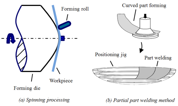
Figure 2. Conventional processing method for thin-walled spherical cap structures.
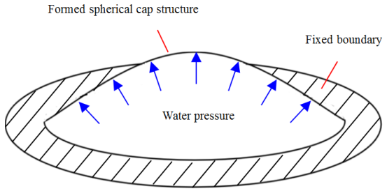
Figure 3. Integrated free-bulge forming method for spherical cap structures.
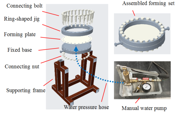
Figure 4. Schematic of the integrated free-bulge forming equipment for spherical cap structures.
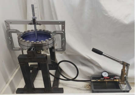
Figure 5. Photograph of the integrated free-bulge forming equipment for spherical cap structures.
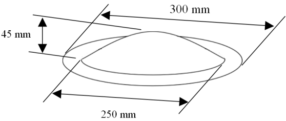
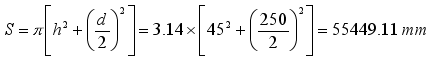
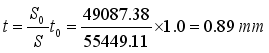
Figure 6. Dimensions of the spherical cap structure produced by the integrated free-bulge forming method.
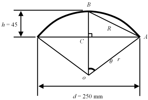
Figure 7. Cross-sectional shape of the processed spherical cap structure.
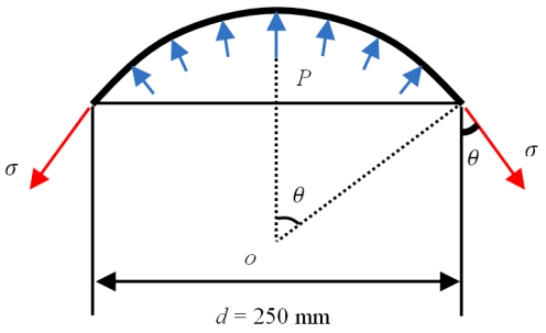
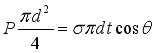
Figure 8. Internal water pressure and stress distributions occurring during free-bulge forming.
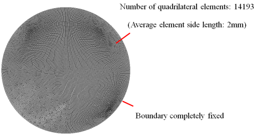
Figure 9. Free bulge forming analysis model using FEM.
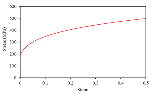
Figure 10. Stress-strain curves of the free-bulge forming plate material.
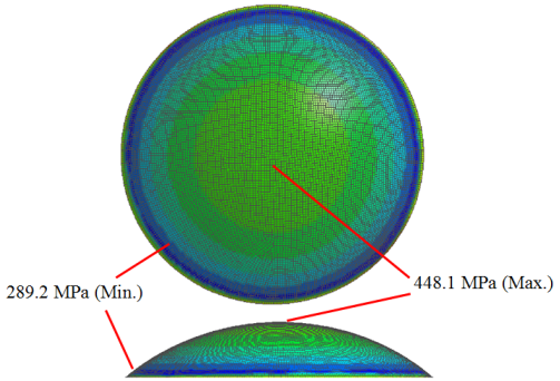
Figure 11. Stress distribution in the free-bulge forming of the spherical cap structure.
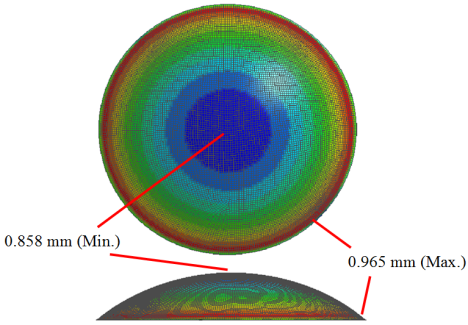
Figure 12. Thickness distribution in the free-bulge forming of the spherical cap structure.
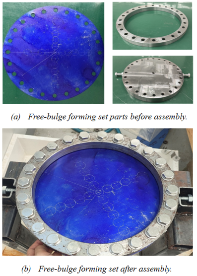
Figure 13. Free-bulge forming set for the spherical cap structure.
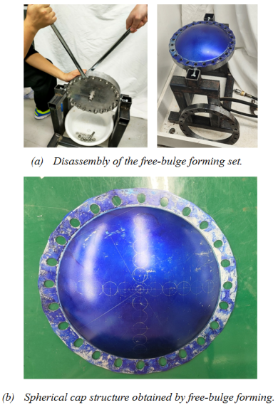
Figure 14. Disassembly of the free-bulge forming set and the resulting spherical cap structure.
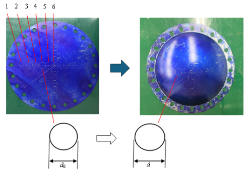
Figure 15. Measuring the plastic strain of the spherical cap structure obtained by free-bulge forming.
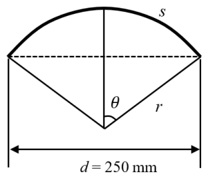
Figure 16. Estimation of the plastic strain in the spherical cap structure.
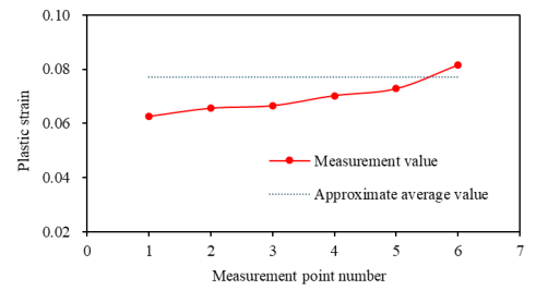
Figure 17. Plastic strain distribution in the spherical cap structure obtained from free-bulge forming.
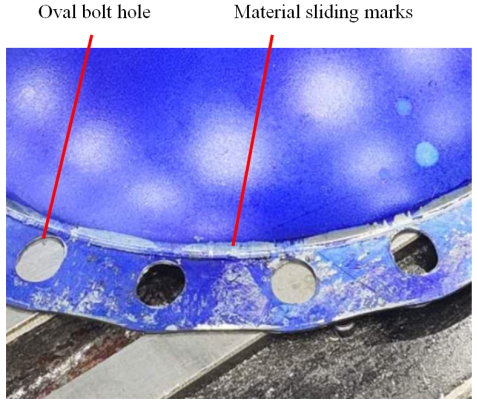
Figure 18. Internal flow phenomenon of the material in the fixed boundary area.
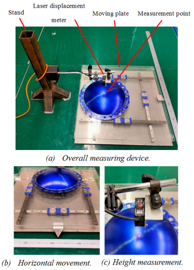
Figure 19. Measuring device for the external surface shape of spherical cap structure.
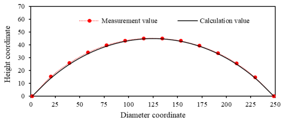
Figure 20. Measurement results of the surface shape of the spherical cap structure.
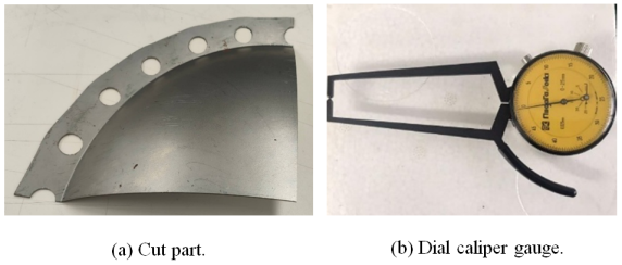
Figure 21. Measurement of the thickness distribution of the spherical cap structure.
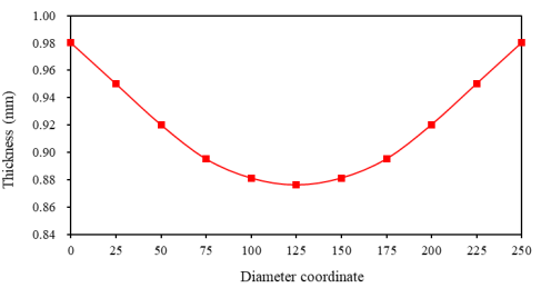
Figure 22. Measurement results of the thickness distribution of the spherical cap structure.